Rust on ESP32 part 2 - The hardware
This is a series of articles about using Rust to program an ESP32 Microcontroller by building a minimal EV Charger.
- Part 1: A Proof of Concept
- Part 2: A minimal EV Charger hardware setup (this article)
- Part 3: Network and Charger to backoffice communication (Wifi/ MQTT / OCPP)
- Part 4: Optional: Charger to Car communication (Mode2)
The previous article was about try-ing to get Rust running on a esp32 microcontroller.
In there I started to set up as a charger for an Electric Vehicle, lets dive more into that by desiging the hardware.
A simple as possible charger should:
- Have a way to detect whether a cable is inserted or not (or simulated by a switch)
- be able to lock the cable with a solenoid (or simulated by a led)
- Allow swiping a card to start charging (or simulated with a button)
- Have a relay to apply power to the cable
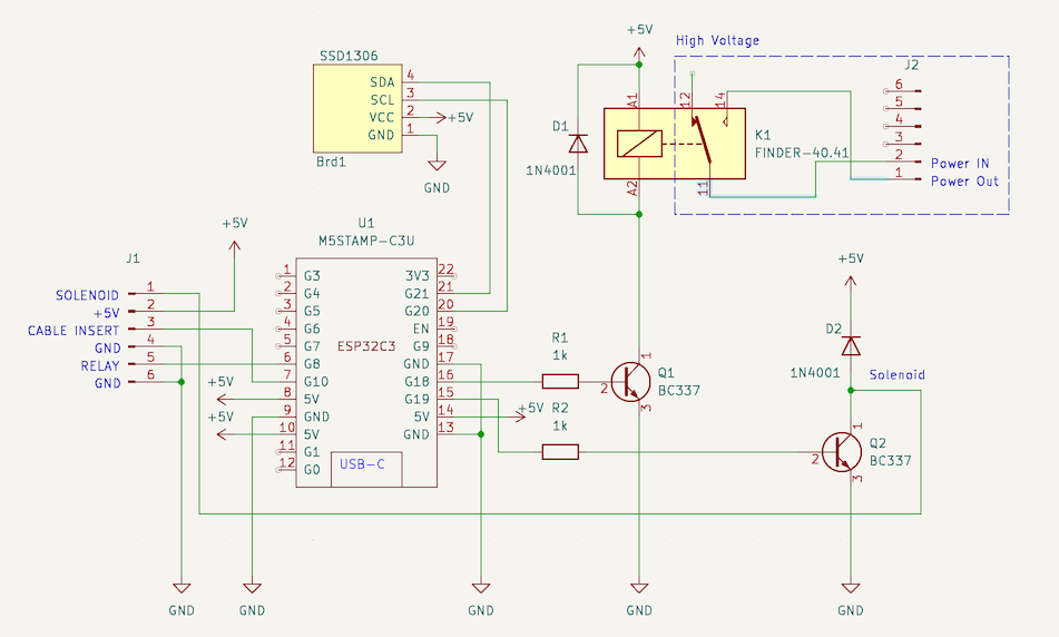
- Visualize the state of the charger (the M5 Stamp has a multicolor led onboard, and I’ve added a small OLED display I had lying around)
Putting all this into a schematic it looks something like this:
Managing State
As a Charger goes through several states during it’s operation (Available, Occupied, Charging, Error) a FSM (Finite State Machine) looks like a good way to model this.
A FSM works as follows:
Whenever something happens (an InputEvent), a cable gets inserted/removed or some form of authentication is provided, a transision is made from one state to the next, resulting in an output event, for instance to tell the charger to lock the cable and start charging.
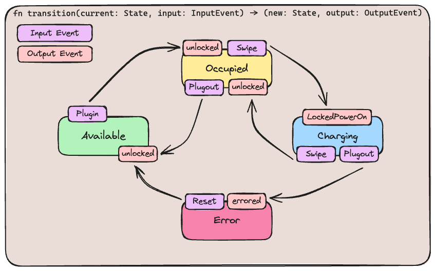
Every Arrow is a transition call with the current State and an InputEvent to a new State with an OutputEvent.
code wise that will look like this:
impl Charger {
    pub fn transition(&mut self, input: ChargerInput) -> Result<(State, ChargerOutput), Error) {
        let output = match (input, self.state.clone()) {
            (ChargerInput::PlugIn, State::Available) => {
                self.set_state(State::Occupied);
                ChargerOutput::Unlocked
            }
            (ChargerInput::PlugOut, State::Occupied) => {
                self.set_state(State::Available);
                ChargerOutput::Unlocked
            }
            (ChargerInput::Swipe, State::Occupied) => {
                self.set_state(State::Charging);
                ChargerOutput::LockedAndPowerIsOn
            }
            (ChargerInput::Swipe, State::Charging) => {
                self.set_state(State::Occupied);
                ChargerOutput::Unlocked
            }
            _ => {
                Err("An invalid transistion occurred")
            }
        }
       Ok((self.get_state(), output))
    }
So now all it left is a bit of logic to do the transitions whenever an event happens
    // setup is skipped, see previous blog, or code

    button.enable_interrupt().unwrap();
    notification.wait(esp_idf_svc::hal::delay::BLOCK);

    match charger.transition(charger::ChargerInput::Swipe) {
        Ok((ChargerState::Charging, charger::ChargerOutput::LockedAndPowerIsOn)) => {
            relay.set_high().unwrap();
            solenoid.set_high().unwrap();
        }
        Ok((_, charger::ChargerOutput::Unlocked)) => {
            relay.set_low().unwrap();
            solenoid.set_low().unwrap();
        }
        ...
    }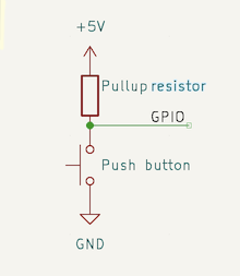
The GPIO Port is configured as input with an pull-up resistor with the button connected to ground, meaning whenever the button is pressed, it will connect the input to ground (0) and when released the pull-up resistor will ‘pull’ it to teh +5V (1) again (creating a Positive Edge (0 -> 1) event).
As we have configured the button in the code to subscribe to a positive edge event, the code will unblock whenever the button is released.
We then call the transition function with the current state and the input event Swipe which will give us a new state Chargng and a output LockedAndPowerIsOn, we then set the hardware to whatever the output is telling us.
So that’s the hardware done, I’ve added a small oled display with an i2c interface, with the rust library that exists for this display, displaying information is a breeze:
let peripherals = Peripherals::take().unwrap();
let i2c = peripherals.i2c0;
let sda = peripherals.pins.gpio21;
let scl = peripherals.pins.gpio20;
let i2c_config = I2cConfig::new().baudrate(100_000.into());
let i2c = I2cDriver::new(i2c, sda, scl, &i2c_config)?;
let interface = I2CDisplayInterface::new(i2c);
let display = Ssd1306::new(
interface, DisplaySize128x64, DisplayRotation::Rotate180).into_terminal_mode();
display.init();
display.clear();
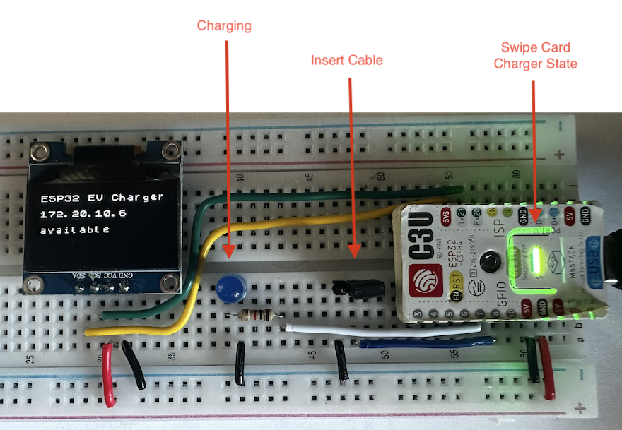
write!(display, "Hello World");Here’s how it looks on a breadboard, I’m using the button and led that are on the m5 Stamp to simulate the swiping of a card and displaying the charger state, a blue led to simulate the relay and a jumper to simulate the inserting of a cable.
The next article will focus on sending and retrieving OCPP Messages to a backend by configuring the Wifi and MQTT Publisher and Subscriber.
references
- Code: https://github.com/gertjana/charger_rust_esp32_c3/tree/cad15fb3a088cdd82d7dbfd5f9d16512b37e4d6f
- esp-idf-template: https://github.com/esp-rs/esp-idf-template
- M5 Stamp ESP32-C3U: https://docs.m5stack.com/en/core/stamp_c3u
- The embedded rust book: https://docs.rust-embedded.org/book/
- Espresiff ESP-32: https://www.espressif.com/en/products/socs/esp32