Rust on ESP32
This is a series of articles about using Rust to program an ESP32 Microcontroller by building a minimal EV Charger.
- Part 1: A Proof of Concept (this article)
- Part 2: A minimal EV Charger hardware setup
- Part 3: Network and Charger to backoffice communication (Wifi/ MQTT / OCPP)
- Part 4: Optional: Charger to Car communication (Mode2)
For the last couple of months, I’ve been learning myself how to program in rust
The main reason was I was intrigued by Rust’s ownership / borrow model, which allows for functional programming, without the need of making everything immutable.
Immutable comes with copying values (instead of passing references) all over the place, which can become an issue when you want to sqeeze every bit of performance out of your application.
As rust is considered more of a systems language, being close to the hardware, using it to write applications for microcontrollers makes sense.
Luckily the makers of the ESP 32 chip espressif also created and maintain a development environment for these chips. What they also did was create a bunch of rust crates that allows access to the chip hardware and features.
There are two modes to write your code, no_std and std
With the no_std, you cannot use Rust its standard library, which makes your application smaller, but you have to do a lot yourself, there are peripheral access and hardware abstraction crates and crates to setup wifi, logging, storage, etc, these are very much device specific. but you have to do all the wiring up.
Therefore I will focus on the higher level std approach which allows the use of all the goodies the standard library brings, plus more device independent abstractions which makes the code much more portable to other ESP32 devices.
Application model
The application model for the std mode look like this:
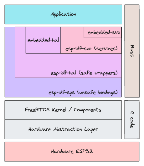
The following libraries are made available
| Library | Description |
|---|---|
| esp-idf-svc | Services like Wifi, Mqtt, Http |
| embedded-svc | device independent api and abstractions for the services |
| esp-idf-hal | safe wrappers around esp-idf-sys |
| embedded-hal | device independent api and common traits for the hardware |
| esp-idf-sys | unsafe bindings to the ESP hardware and features |
A filtered out dependency tree from cargo tree shows how the libraries depend on each other
├── esp-idf-hal v0.42.5
│   ├── embedded-hal v0.2.7
│   ├── esp-idf-sys v0.33.7
├── esp-idf-svc v0.47.3
│   ├── embedded-svc v0.26.4
│   ├── esp-idf-hal v0.42.5
|   ├── esp-idf-sys v0.33.7
Use case
As my daily work is all about allowing EV Drivers to charge their cars, I’ve decided to make a small EV charger
For this I need to control GPIO (General Purpose Input Output) Pins to enable charging (relay), lock the cable (solenoid), display the charger state (multicolor led) and communicate to a backend (MQTT / IoT)
hardware
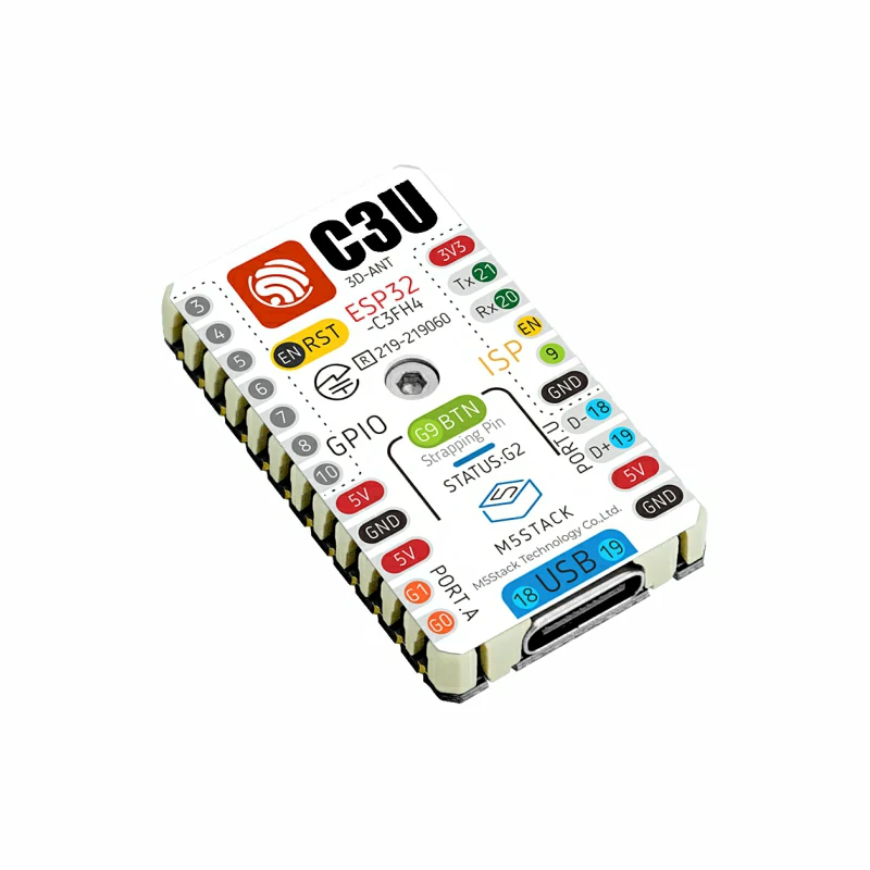
I decided to use a M5 Stamp C3U that I had lying around which is based on the ESP-32 C3U chip, a 1 core 32 bits RISC-V cpu running on 160Mhz
It has 400Kb RAM and 4Mb Flash and has Wifi and Bluetooth capabilities
There are 14 GPIO Pins, that can be setup als digital or analog input/ouput, and some of them use serial protocols like UART, I2C, I2S and SPI so plenty to play around with
setup
To get started I used the cookiecutter template Espressif has created: https://github.com/esp-rs/esp-idf-template
This should also be your starting point, if you want to play with it yourselves.
After installing the prerequisites a simple
cargo generate esp-rs/esp-idf-template cargowill after answering a few questions generate a project for you.
to build and flash it hook up your device to an usb port and do
> cargo build
   Compiling rust-esp-charger v0.1.0 (/Users/gertjan/Projects/rust-esp-charger)
    Finished dev [optimized + debuginfo] target(s) in 1.96s
and then:
> espflash flash target/riscv32imc-esp-espidf/debug/rust-esp-charger
[2024-01-04T12:53:07Z INFO ] Detected 4 serial ports
[2024-01-04T12:53:07Z INFO ] Ports which match a known common dev board are highlighted
[2024-01-04T12:53:07Z INFO ] Please select a port
❯ /dev/cu.usbmodem1101 - USB JTAG_serial debug unit
  /dev/tty.usbmodem1101 - USB JTAG_serial debug unit
  /dev/cu.Bluetooth-Incoming-Port
  /dev/tty.Bluetooth-Incoming-Port
[2024-01-04T12:54:07Z INFO ] Serial port: '/dev/cu.usbmodem1101'
[2024-01-04T12:54:07Z INFO ] Connecting...
[2024-01-04T12:54:07Z INFO ] Using flash stub
Chip type:         esp32c3 (revision v0.3)
Crystal frequency: 40MHz
Flash size:        4MB
Features:          WiFi, BLE
MAC address:       84:f7:03:27:96:ec
App/part. size:    559,520/4,128,768 bytes, 13.55%
[00:00:04] [========================================]     271/271
[2024-01-04T12:54:13Z INFO ] Flashing has completed!
The target might differ depending on the type of your ESP32 , but the rest should be the same.
If you do
> espflash monitorIt will show you all the messages logged to the console, you can also add --monitor to the flash command to do it in one go
The Code
My first thoughts were that I would have to create multiple running tasks, that would handle controlling the hardware and communicating with the backend. so first I had to find out how to do that in rust and how I can communicate changes to those tasks.
As the C code IDF Framwork is based on the FreeRTOS Kernel, I knew about things like xTaskPinnedToCore() which runs a task in parallel to the main thread, and the xQueue* API to send receive messages between tasks, unfortunately xTaskPinnedToCore() only allows C functions as a parameter, so no Rust goodies in there (or at least not to my knowledge, what’s the signature of a rust function in C?)
But as I can use the standard library, std::thread::spawn is available to which I can pass a closure, but how to communicate changes?
When you access a variable in the closure that is defined outside of the closure the compiler will make you use the move keyword to explicitly move ownership to the closure.
So for instance: if you have a simple Charger struct that has a field state, which holds the state of the charger (Available, Occupied, Charging, Error)
and you want to access that from within the thread, the compiler will complain about the last line that the charger’s ownership has moved to the thread. as seen in the snippet below
let mut charger = Charger{id: "1", state: "Available"}

thread:spawn(move || {
    println!("Charger from thread: {:?}", charger);
    loop {
        charger.state = "Charging";
        // sleep a bit
    }
});

println!("Charger from main: {:?}", charger);
To solve this we need to use two concepts from rust synchronisation utilities.
std::sync::Arc<T>Arc stands for Atomically Reference Counted, This will keep a reference for each time you clone the object, and makes sure the original object is updated with any changes.std::sync::Mutex<T>A Mutex will lock the object so only one thread can update the object at a time
So to get the above working:
let org_charger: Arc<Mutex<Charger>> = Arc::new(Mutex::new(Charger{id: "1", state: "Available"}));

let charger = org_charger.clone();
thread:spawn(move || {
    println!("Charger from thread: {:?}", charger);
    loop {
        charger.state = "Charging";
        // sleep a bit
    }
});

let charger = org_charger.clone();
loop {
    println!("Charger from main: {:?}", charger);
    // sleep a bit
}
Note that because the charger moves into the thread, I can reuse the charger var as the first one is no longer in scope, also note that the object does not need to be mutable anymore.
Now how to control the leds, relays, buttons that are needed to make this charger functional?
That’s done through the “General Purpose Input Output” or GPIO, working with GPIO is pretty straightforward:
Here we turn a led on when a button is pressed.
use esp_idf_hal::delay::FreeRtos;
use esp_idf_hal::gpio::*;
use esp_idf_hal::peripherals::Peripherals;

let peripherals = Peripherals::take()?;
let mut led = PinDriver::output(peripherals.pins.gpio4)?;
let mut button = PinDriver::input(peripherals.pins.gpio9)?;

button.set_pull(Pull::Down)?;

loop {
    // we are using thread::sleep here to make sure the watchdog isn't triggered
    FreeRtos::delay_ms(10);

    if button.is_high() {
        led.set_low()?;
    } else {
        led.set_high()?;
    }
}
Doing a button in a more async ‘wait until pressed then do something’ is a bit more involved:
First set up the button and an interrupt:
use esp_idf_hal::peripherals::Peripherals;
use esp_idf_svc::hal::gpio::{InterruptType, PinDriver, Pull};
use esp_idf_svc::hal::task::notification::Notification;

let mut button = PinDriver::input(peripherals.pins.gpio9)?; // pin 9 is the onboard button on the M5 Stamp C3U
button.set_pull(Pull::Up)?;
button.set_interrupt_type(InterruptType::PosEdge)?;

let notification = Notification::new();
let notifier = notification.notifier();

unsafe {
    button
        .subscribe(move || {
            notifier.notify_and_yield(NonZeroU32::new(1).unwrap());
        })?;
}
Here we have created an interrupt that will notify when the button is pressed in this case on a Positive Edge (when the button is released).
Now we can enable the interrupt and block until it is interrupt by someone pressing the button.
loop {
    button.enable_interrupt()?;
    notification.wait(esp_idf_svc::hal::delay::BLOCK); // code blocks until button interrupts
    println!("Button was pressed and released");
}
We do this in a separate thread so it won’t block the rest
The M5 Stamp that i’m using has an onboard multicolor led (SK6812 chip) attached to a gpio port, there is a rust library for that and other multicolor led, or ledstrips call smart_leds
use smart_leds_trait::{SmartLedsWrite, White};
use ws2812_esp32_rmt_driver::driver::color::LedPixelColorGrbw32;
use ws2812_esp32_rmt_driver::{LedPixelEsp32Rmt, RGBW8};

fn main() -> Result {
    let driver = LedPixelEsp32Rmt::<RGBW8, LedPixelColorGrbw32>::new(0, 2)?; //Onboard led is attached to pin2
    let red = RGBW8::from((255, 0, 0, White(0)));
    let color = std::iter::repeat(red).take(1);
    driver.write(color)?;
}
In the code linked at the bottom, I combined all the above in an application that runs on the ESP32-C3U and will cycle through all the charger states when the onboard button is pressed. showing the correct color on the onboard led and output the charger state in the console.
Proving that you can run Rust on an ESP32, access the hardware and run code concurrently while being able to access shared objects.
Thanks for reading, the next articles will most likely expand on this and be about:
- Controlling a minimal hardware setup for a charger (Relay, Led, Button) based on the charger’s state
- Setup Wifi and MQTT to communicate with a backend, using the OCPP protocol
- Optionally: Control Pilot (CP) communications between the charger and the car over a Type2 Mennekes connector
References
- Code: https://github.com/gertjana/charger_rust_esp32_c3/tree/806cba4c933c5211d2c4f4759c223452b8426158
- esp-idf-template: https://github.com/esp-rs/esp-idf-template
- M5 Stamp ESP32-C3U: https://docs.m5stack.com/en/core/stamp_c3u
- The embedded rust book: https://docs.rust-embedded.org/book/
- Espresiff ESP-32: https://www.espressif.com/en/products/socs/esp32