Experimenting with AI in FPGA Development
implementing an SPI controller in an FPGA and testing if it works with a logic analyzer before adding an actual Device
The Premise
As an exercise to see how 'good' LLM's are getting I've asked it to build a small CPU (The likes of the Z80 or 6502) in an FPGA I had in a drawer, that project can be found here if you're interested
That is all working nice and dandy, giving me a chance to write some small assembly programs for it, bringing back fond memories from my youth.
Improving the situation
But where it comes to visualisation, the MAX1000 FPGA board has 8 leds in a row, which I use to show the Program counter and the Carry and Overflow flags and with a push of a button the contents of one of the 8bit registers.
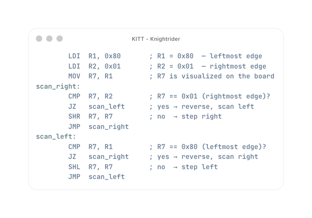
For instance here it is running a program, that uses the SHL (Shift left) and SHR (Shift right) instructions to simulate the light pattern on the KITT car from the Knightrider television series
Moar visuals
So lets add a small OLED Screen, the board has an 12 pin connector to interface with the outside world in a standardized manner, and you can buy amongst other things a 128x32 OLED Display based on the SSD1306 chip which has an SPI Interface to be able to control it.
Now while the display is on order. I started the SPI Implementation. (It's a bit different from working with Arduino's as they have loads of libraries available)
SPI requires at least 4 wires
- Enable (or Clock Select) low is telling the device on the other end. I'm going to send you some data now
- D/C (Data/Command) High meaning i'm sending data (text or pixels), Low meaning I'm sending you commands f.i. clear screen, set cursor
- MOSI (Master out, Slave in) the actual data
- Clock (Pulses for each data bit that is send out)
So Opencode with Claude Sonnet 4.6 in plan mode, I started warming it up to the SPI implementation. giving it links the the SPI protocol itself and the datasheet for the SSD1306 Display model and then asked it to implement a monitor that would show the content of the registers and flags, and the name of the program it is running.
The resulting code is here rtl/oled_monitor.v
So far so good It created the implementation and tests for the testbench simulator but I wanted to be more sure that it would work. the LLM had similar ideas, as it was asking about what should we do next? One of it's suggestions was to hook up an logic analyzer so I could judge whether or not it was correctly implemented.
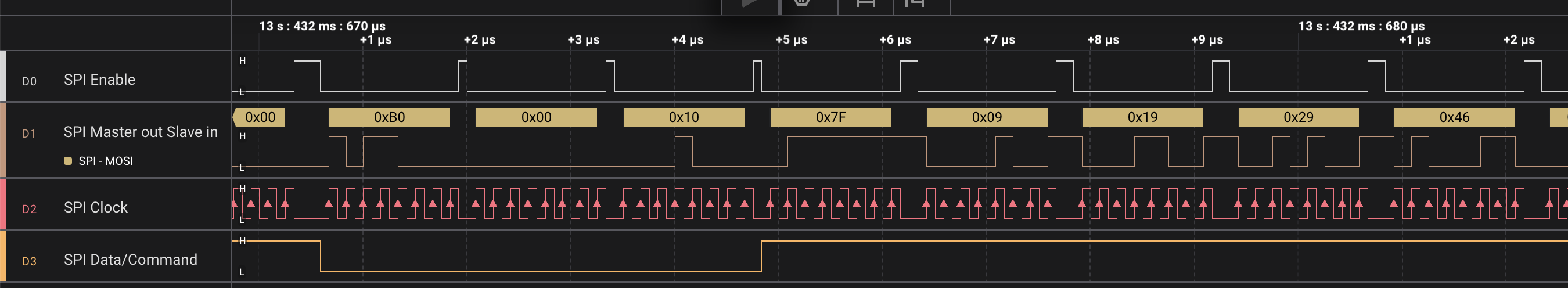
So I hooked up a logic analyzer, set the protocol to SPI, so it recognizes the bytes of data, and let it run for a bit, the result is shown below
Feedback loop
Now the idea I had then is to feed that image back into opencode and ask it to use the logic analyzer screenshot to verify the implementation itself.
It did so, relating the code and timings to the SPI output and even found a couple of bugs:
In summary:

1	DC possibly one byte late for first font byte per line (visible in screenshot as 0x7F sent with DC=0)
  High — display shows garbage on first column of each line's first char after page-set
2	Display On (0xAF) sent before VBAT+100ms delay, violating power-on sequence
  High — could damage display or fail to initialize
3	Reset applied before VDD is on
  Medium — deviates from Digilent spec
4	ST_DISP_ON state is dead code
  Low — code smell
5	SPI engine and FSM both modify spi_cs_n in same cycle when spi_done
  Medium — works in simulation but fragile in synthesis

The most directly confirmed bug from the screenshot is Bug 1 (DC=0 for the first font data byte after page commands), and Bug 2 (Display On sequencing). Would you like me to fix any of these?
Asking it to fix it and repeating the exercise, I got a thumbs up. making the risk of this not working as low as possible, but still there, so there's still the possibility I have to dive into the datasheet. to look at probably timing issues. but fingers crossed.
Conclusion
This way of working proofs that LLM's can make you pretty productive, but you need to make sure it has the right context and good feedback on what it has done.
I also gave Claude the capture file with all the measurements, but that turned out to be too much for it. it went under and never surfaced again.
What could we have done better? well, what we want to display, the fonts and the actual SPI protocol is all in one file. In a normal application that would be split up in the SPI implementation module with a clear interface. to be called from the application. but for a Proof of Concept this is fine.
Can't wait for the display to arrive